[教學影片] STM32 Cube vs Duino 開發環境 #Arduino教學 24
教學影片中簡介 STM32Cube 以及 STM32duino 兩種開發環境。
影片中的相關教學文章 :

在這篇 [STM32] Why STM32 ? 筆記裡,我列出了我購買 STM32 的原因,以及STM32 開發環境的選項,其中一項軟體開發環境就是 STM32duino,所以這篇就來說明如何將 STM32 Arduino package 加入 Arduino IDE,然後透過 "Blinking LED”範例的操作,各位就可以和這篇 [STM32] Hello STM32Cube with Blinking LED 做一個 CubeIDE 和 Arduino IDE 的比較。
Install STM32 BSP into Arduino IDE
簡潔的說,就是和 ESP8266 / ESP32 的操作步驟是一樣;就是將下面的 URL 加到 Arduino IDE 的 “Additional Boards Manager URLs”內,然後安裝 STM32CubeProgrammer,因為 Arduino IDE 會呼叫它做 firmware 的 upload 。
https://github.com/stm32duino/BoardManagerFiles/raw/master/STM32/package_stm_index.json
Step 1: 開啟 Arduino IDE,接著點選 “File -> Preference”,然後如下圖,將上面 URL 加入“Additional Boards Manager URLs”的 diallog 內。
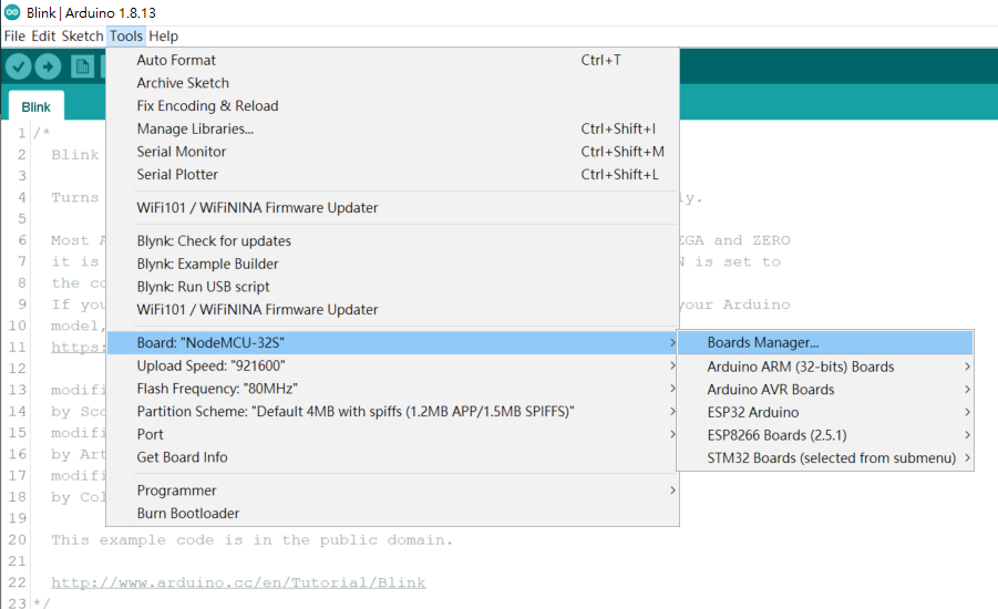
Step 2: 在上一步驟按下 "OK" 後,接著點選 “Tools -> Board ->Boards Manager...”。
接著在 Boards Manager 視窗輸入 "STM32”,然後將 “ STM32 Cores”下載安裝起來。
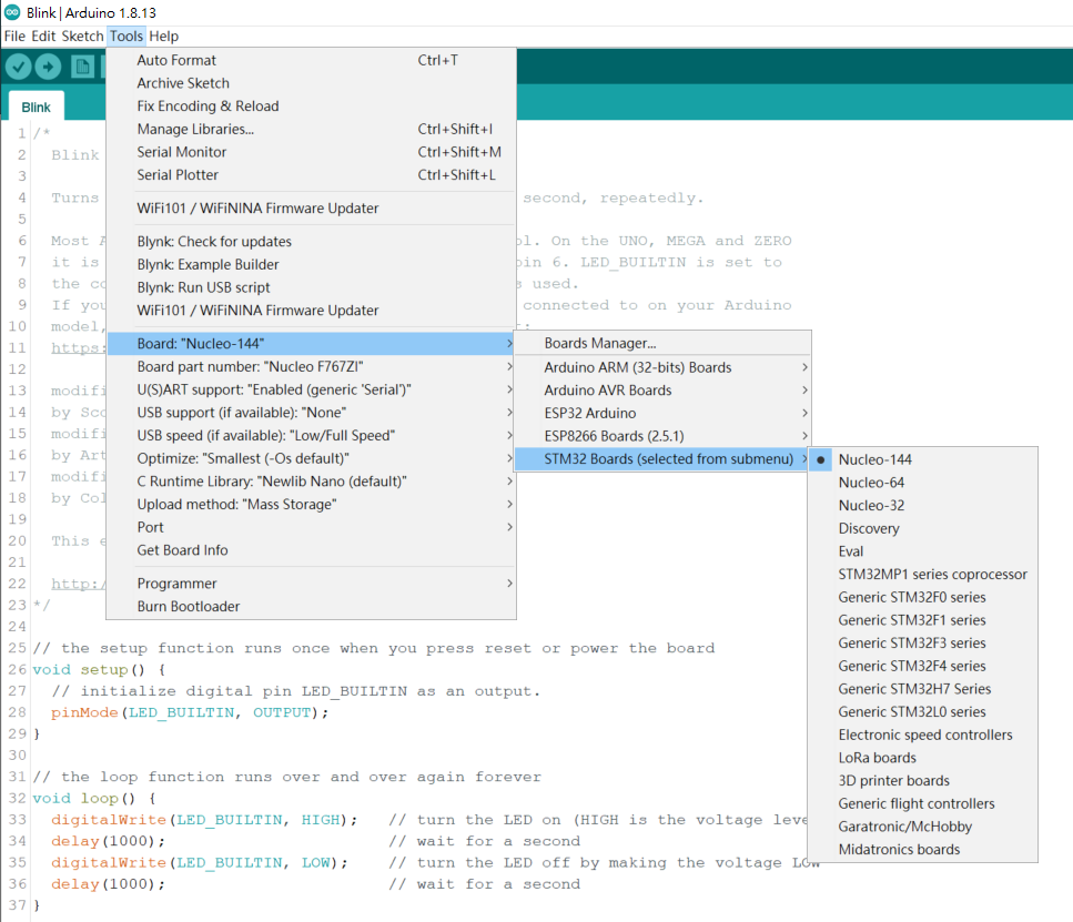
待 STM32 BSP (Board Supported Package) 安裝完成後,再次點選 “Tools -> Board ->Boards Manager...”,就可以看到如下圖,"STM32 Boards" 的選項出現在 Arduino IDE 的 Boards Manager 的清單內了。
Step 3: 到 ST 官網下載 " STM32CubeProgrammer" 然後安裝它。
因為 Arduino IDE 需要透過 STM32CubeProgrammer 來做 firmware 的 upload 。
==================================================
Blinking LED with Nucleo-F767ZI Board
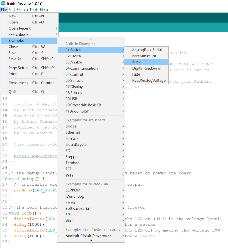
Step 1: 開啟 Arduino IDE,接著點選 “File -> Examples -> 01.Basic -> Blink”。
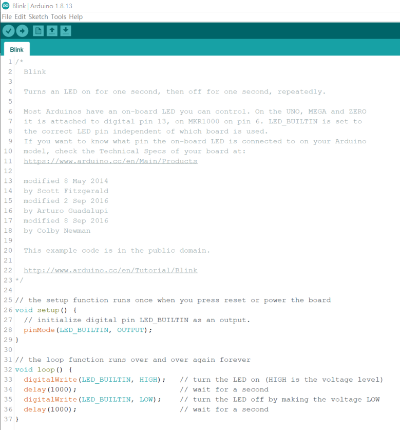
Arduino IDE 就會載入"Blink”的範例程式碼,如下圖 。
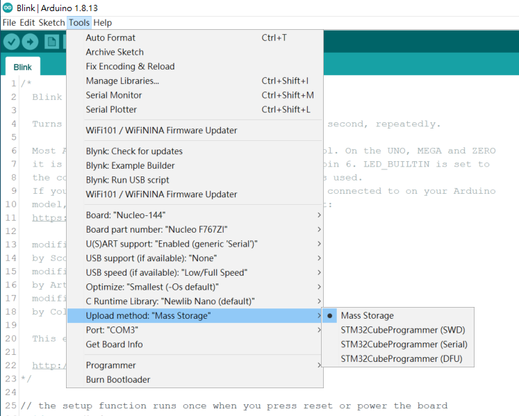
Step 2: 接著點選 “Sketch -> Upload”,Arduino 就會依照你的設定 Upload new firmware。
到這裡,你不妨比較一下 STM32CubeIDE 和 Arduino IDE 的差異。
但有一點,我要告訴大家的是,ST 官方提供的 STM32CubeIDE 能透過 ST-Link 做到 real-time debugging 功能 (SWD, JTAG),這點是 Arduino IDE 無法做到的,若你是 Advance User 或是做比較複雜的專案,real-time debugging (SWD, JTAG) 這功能你是需要的,千萬不能放掉 STM32CubeIDE 這個開發環境的。
以上參考資料來自
https://www.arduinolibraries.info/authors/stm32duino
透過 ”設定 Profile Background” 再加上風力以及火力的紀錄,真的可以達到 "重現" 烘培曲線嗎 ?
於是,今天準備了 3 份 200 克的 "巴拿馬水洗百合花" 來測試一下了喔!
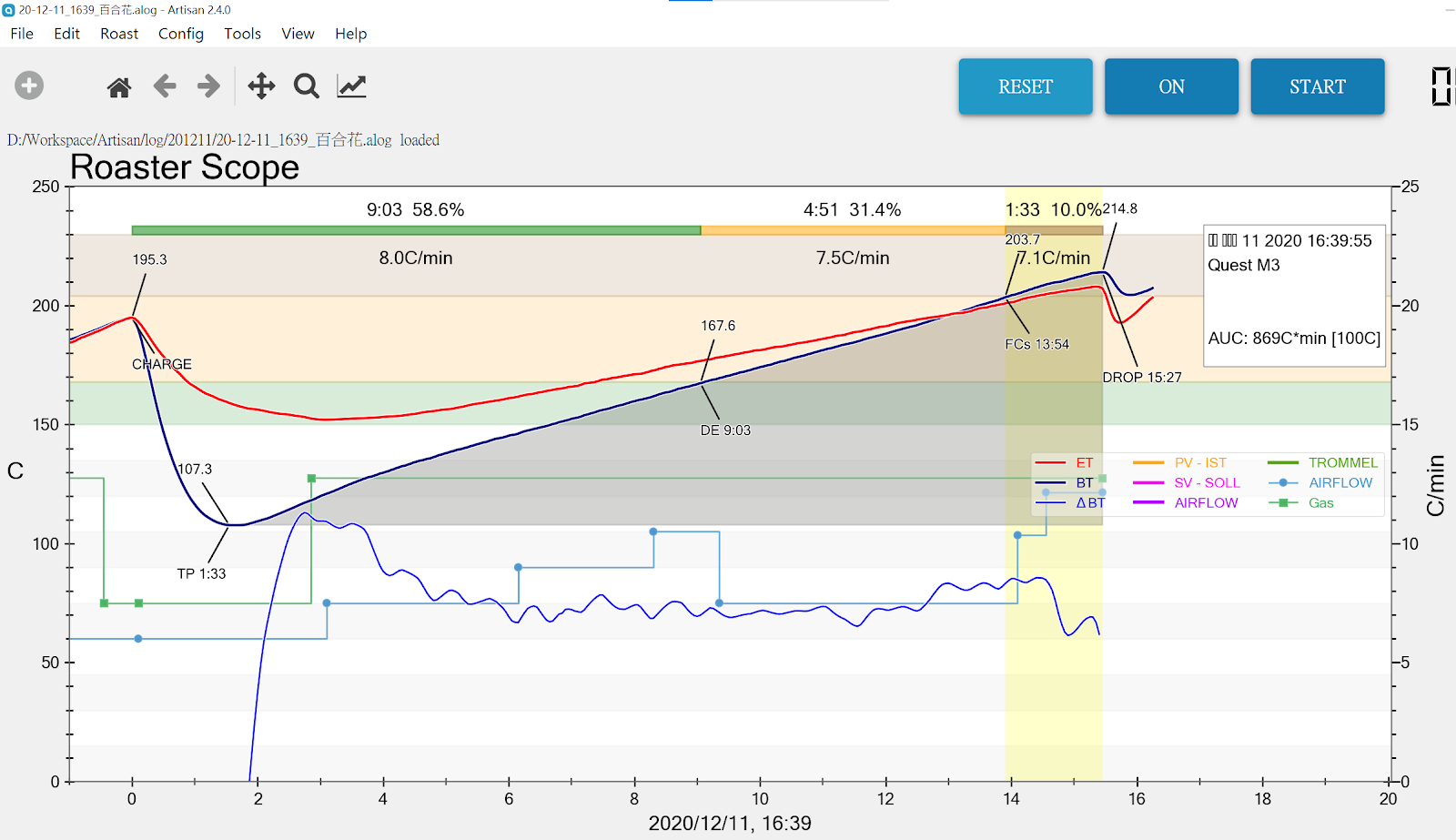
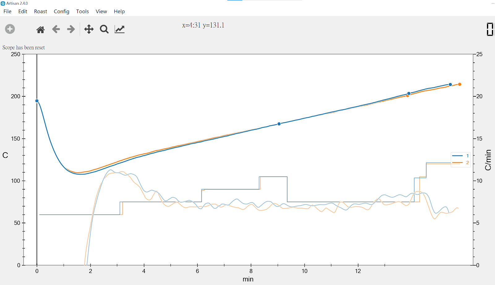
這是第一鍋的烘培曲線
下豆溫度在 214.8 度,烘培時間是 15:27
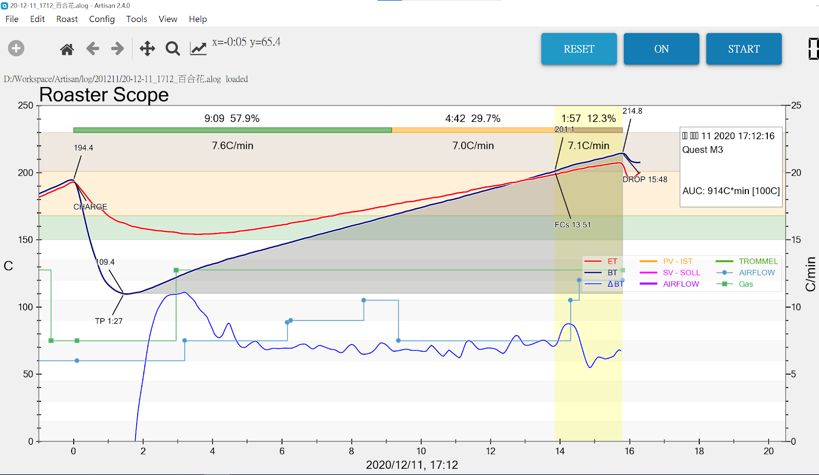
第二鍋就以第一鍋的烘培曲線為藍本,下圖就是第二鍋的烘培曲線
下豆溫度也在 214.8 度,烘培時間則是 15:48
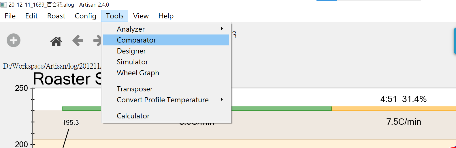
透過 Artisan "Comparator” Tool ,來看一下兩鍋烘培曲線的差異
下圖則是兩曲線的比較圖 ,個人覺得很滿意,那你呢 ?
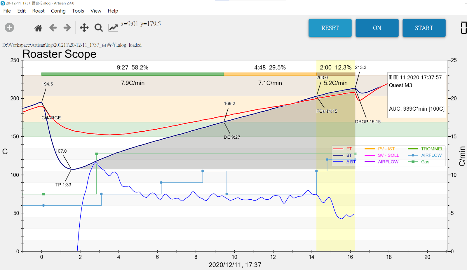
第三鍋同樣以第一鍋的烘培曲線為藍本,下圖就是第三鍋的烘培曲線
下豆溫度也在 213.3 度,烘培時間則是 16:15
PS: 在烘焙過程中,發現第三鍋的烘培時間有點拉長了,所以我刻意提前下豆溫度
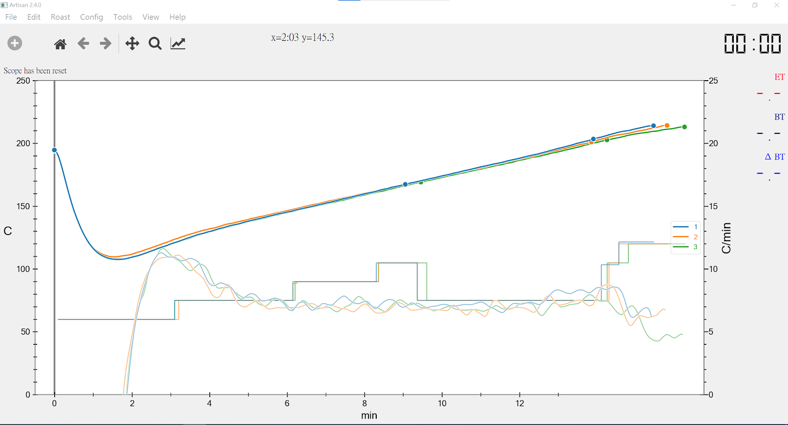
下圖則是 3 曲線的比較圖 !
心得:
透過 Arduino 的資源,以 UNO 這塊板子來模擬 TC4 的功能,然後結合 Artisan 咖啡烘焙軟體, 就能在 Quest M3 這台機器上達成 "重現" 咖啡烘培曲線,你還能不滿意這結果 !?
先前在收到 ESP-CAM 這塊開發板時,曾經在 Ubuntu 下 build 過 ESP32 的 原始碼,
請參考這篇文章 ESP32-CAM ( Ai-Thinker Module )。
最近在玩 MicroPython (MP) ,想深入研究 MP,就必須自己 Build Code 研究,
上次 (ESP32-CAM ( Ai-Thinker Module )) 沒把過程詳細記入下來,
如今在 Ubuntu VM 下又實作一次,又是跌跌撞撞的,做到一半就想把過程步驟寫下來,
希望對日後有幫助。
這次改在 Ubuntu 18.04 VM 來建立開發環境,方便 Ubuntu 以及 Windows 10 同時操作
,文章也可即時撰寫。不廢話了,進入步驟描述吧!
1.1 Change directory to your working directory
1.2 Create an ESP folder at your working directory
sudo mkdir -p esp
cd esp
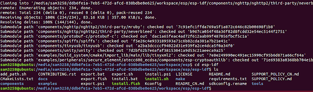
1.3 Download ESP-IDF under esp folder
sudo git clone --recursive https://github.com/espressif/esp-idf.git
Result from step 1
2.1 Change directory to /esp-idf by below commands
cd esp-idf
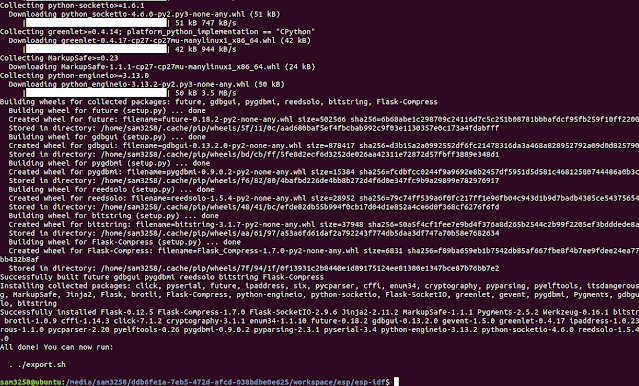
2.2 Execute below command to install ESP-IDF Tools
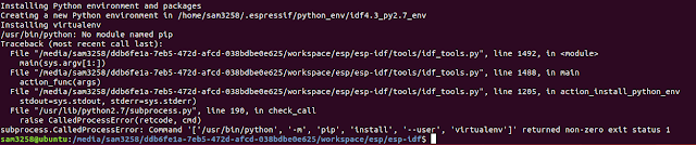
./install.sh
2.3 做到這一步,還是因為新裝好的 Ubuntu 18.04 VM,還沒裝任何 Package,
Python 以及 Python-pip 沒有安裝。
Please execute the below commands to install them。
sudo apt-get install python
sudo apt-get install python-pip
If you want to install Python3, run below commands
sudo apt-get install python3
sudo apt-get install python3-pip
After installed Python package if you still meet below error
/usr/bin/env: ‘python’: No such file or directory
Please execute below commands to create a symlink
sudo ln -s /usr/bin/python3 /usr/bin/python
Result from step 2
3.1 Every time, you want to build code before, please run below
command to setup the environment variables
. ./export.sh
or
. $HOME/esp/esp-idf/export.sh
Result from step 3
4.1 Copy built-in example "Blink" under \esp folder
cd $IDF_PATH/..
sudo cp -r $IDF_PATH/examples/get-started/blink .
4.2 Need cmake tool before build, please run below command to install it,
otherwise you will get an error as below
sudo apt-get install cmake
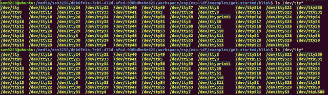
5.1 Run below command before and after to get serial port number
ls /dev/tty*
In my result, the serial port number from my two runs is
/dev/ttyUSB0
6.1 Configure target build by execute below command
idf.py set-target esp32
PS: Setting the target with idf.py set-target esp32 should be
done once, after opening a new project.
If the project contains some existing builds and configuration,
they will be cleared and initialized.
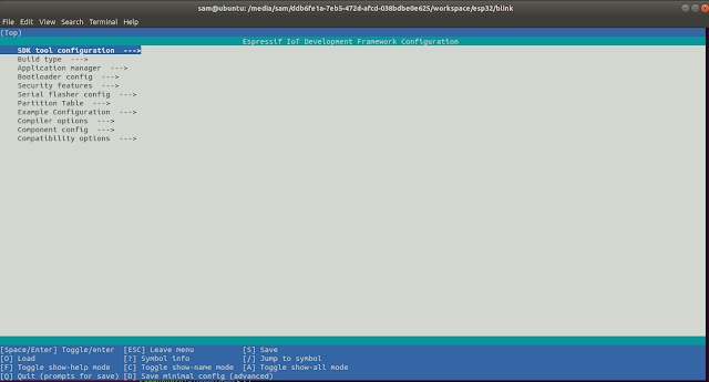
6.2 Execute below command to check build environment,
the following menu will appear if previous steps are correct.
idf.py menuconfig
idf.py build
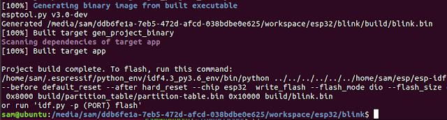
Build Complete Result
sudo chmod 666 /dev/ttyUSB0
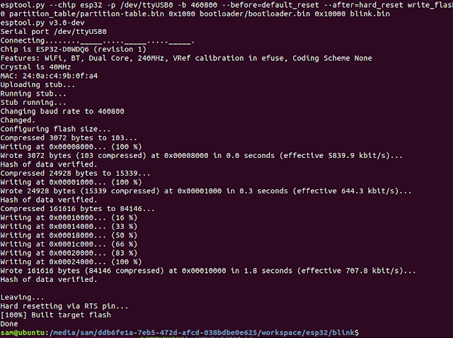
idf.py -p /dev/ttyUSB0 flash
前面 ESP-IDF 的版本是使用 Master / 當時 Latest 的版本, 並非正式 Release 版本,
在 Build MicroPython Image 時遇到了問題,因為 MicroPython 只支援 ESP-IDF v3.0
以及 v4.0,所以我就重新安裝成 MicroPython 所支援的 v4.0。
重新再 Build 一次 Blink Project 發現 v4.0 和 Master 的差異有些大。
以下就是差異點 :
1. “idf.py set-target esp32” command is not support,直接下“idf.py menuconfig”
2. 下“idf.py menuconfig”command 後,會有一堆 Errors,那是因為還缺一些 packages
要再執行以下commands 安裝 packages
$ sudo apt-get install libncurses5-dev libncursesw5-dev
$ sudo apt install flex gperf bison
這樣才能順利執行 “idf.py menuconfig”以及“idf.py build”
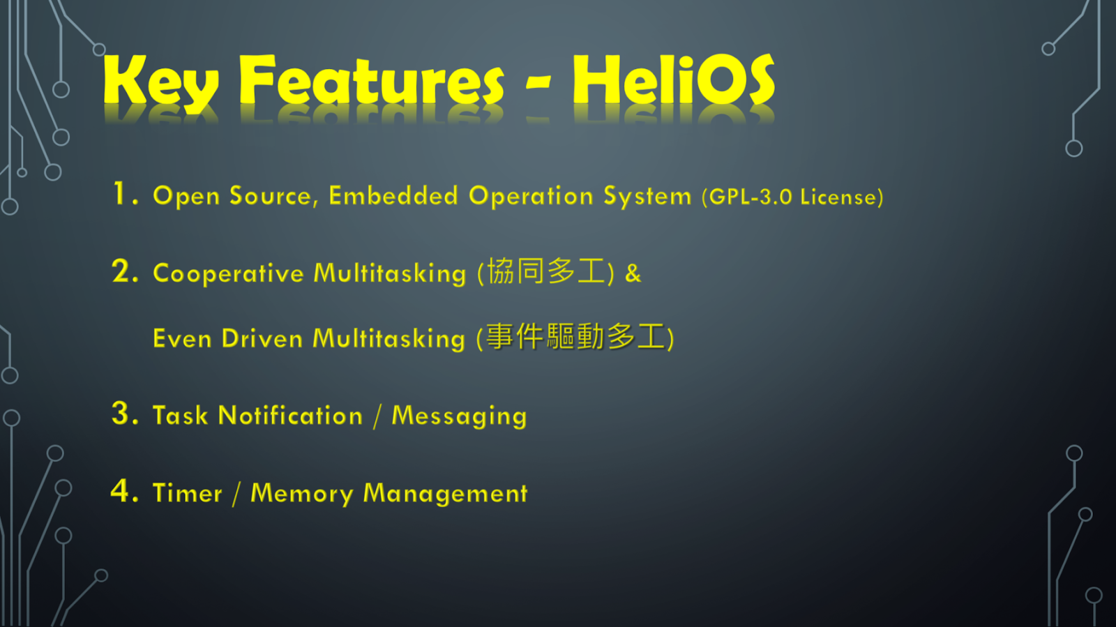
HeliOS 的特點:
Open Source 的 Embedded OS (Operation System),是 GPL-3.0 的License,也就說,對於專題製作而言就是免費的 。
採用協同式多工 ( Cooperative Multitasking ) 以及事件驅動式多工 (Even Driven Multitasking ) 的方式做Task 的切換。
Task 之間可以透過 Notification / Messaging 做資料訊息的傳遞。
一般的 Embedded OS 都有的功能,如計時器和記憶體的管理,它也有提供。
以上這幾項特點都是制式說法,不是我主要推薦給大家的原因, 而我推薦的理由有以下三點
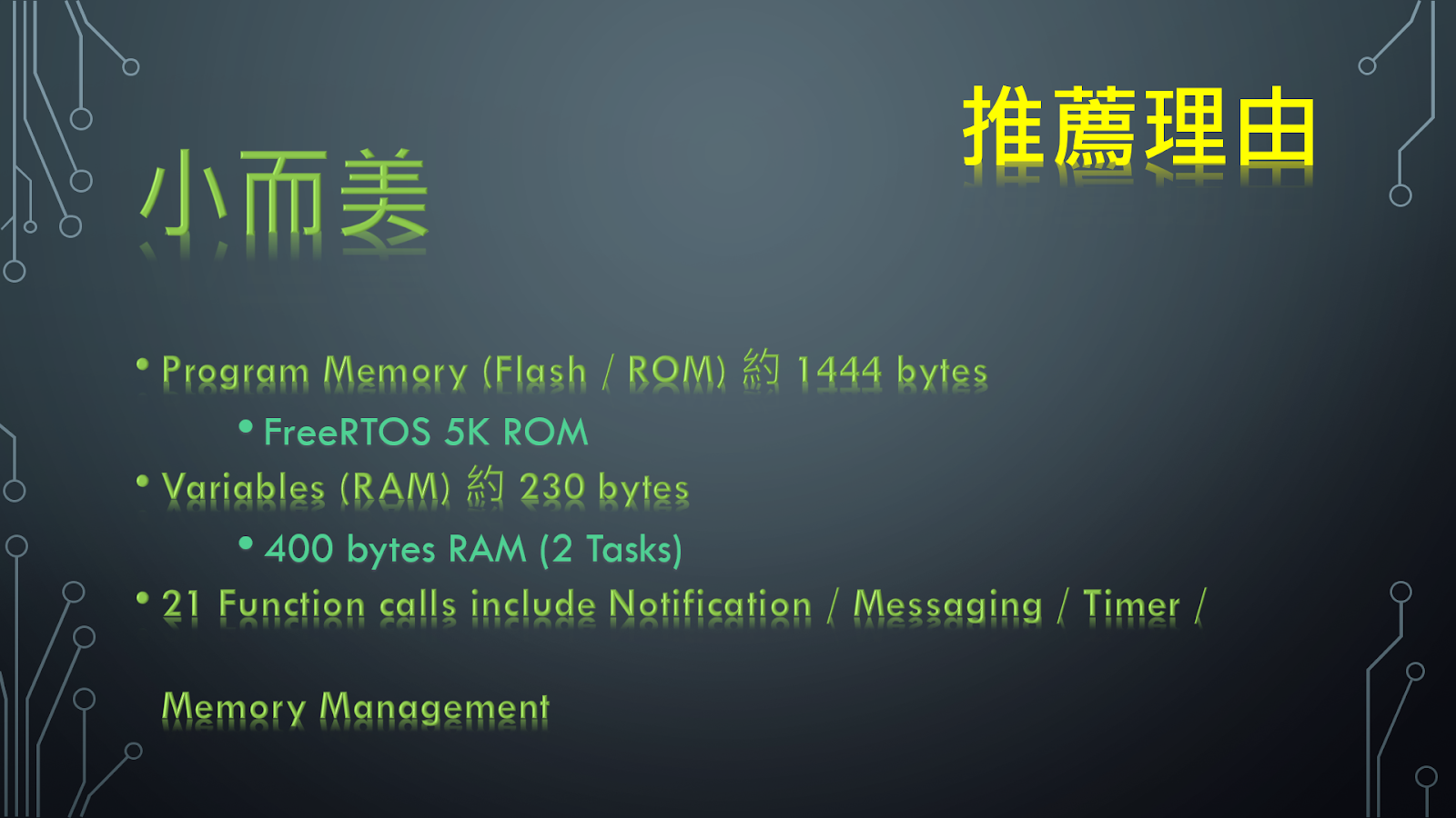
小而美 :
以我改寫咖啡烘培程式的實作為例,HeliOS 佔用的記憶體空間,Program Memory (ROM) 則是約 1400 bytes, Variables (RAM) 則是 230 bytes,這絕對是 embedded OS 最小的;對比於 FreeRTOS 至少需要 5K ROM, 400 bytes RAM (以 2 Tasks 計算),記憶體空間以及複雜度,HeliOS 是絕對小而美,但小歸小,五臟則俱全,Embedded OS 基本該有的 Notification / Messaging / Timer / Memory 的功能,他都有喔,對於專題製作的需求也是綽綽有餘的!
容易上手 :
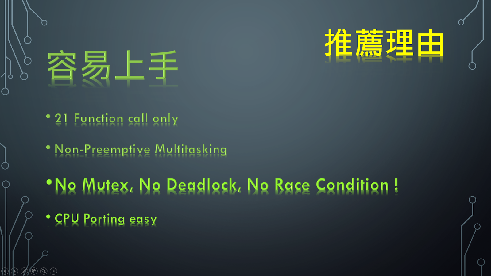
再來則是容易上手,沒有負擔;只有 21 個 System Function Call,花 1~2 個小時研究一下,絕對就可以上手使用它。再加上是協同式多工(Cooperative Multitasking ),不是佔先式多工 (Preemptive Multitasking),也就沒有 Mutex, Deadlock, Race Condition 這些擾人難解的疑難雜症了;也因為是協同式多工 , Porting 到不同 CPU ,不須動用到組合語言就可以輕鬆移植到不同的單晶片上,CPU Porting 的困難度相對於 RTOS 就低很多了 !
程式發展不受限 :
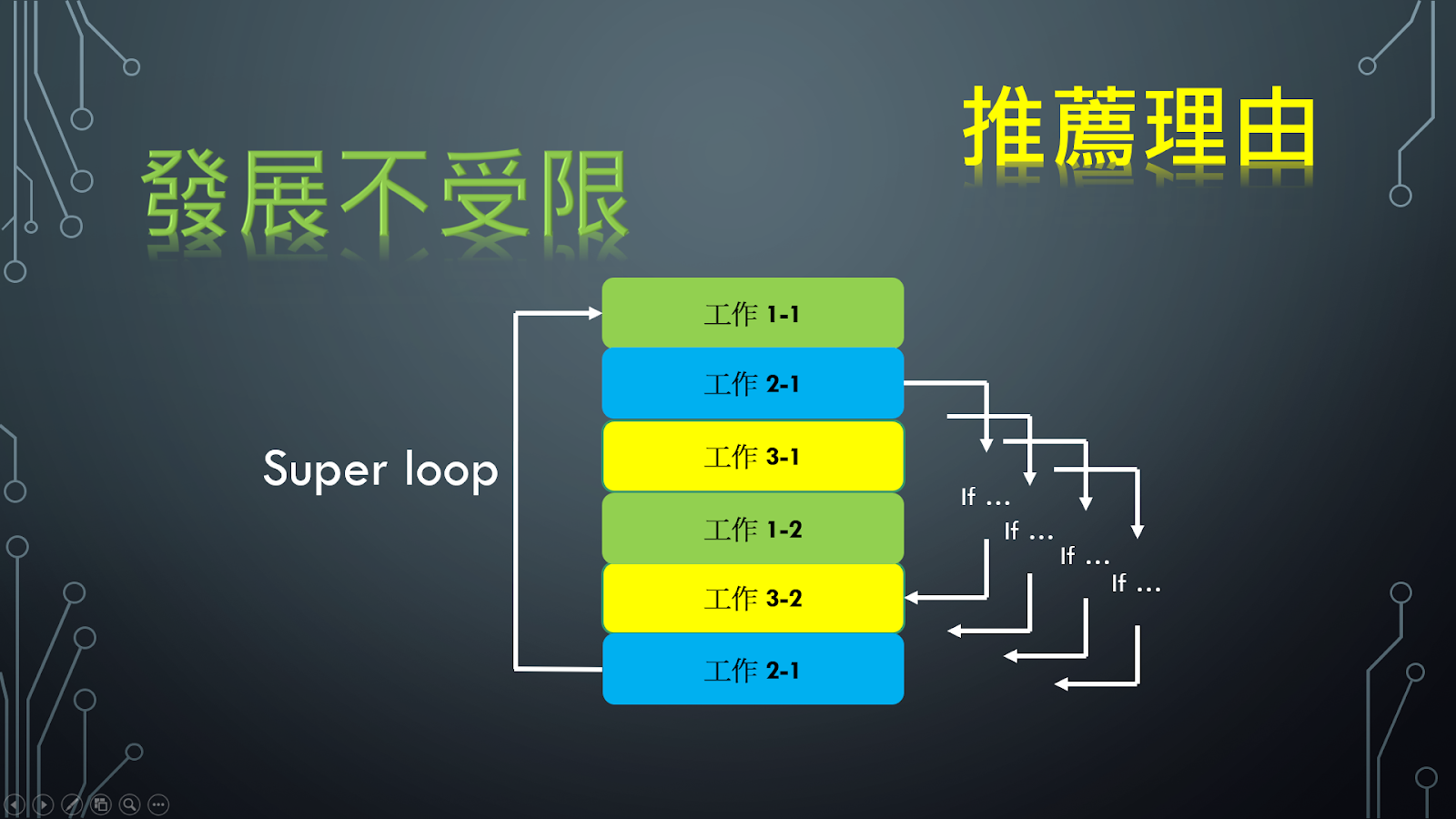
最後一點則是程式發展不受限;這項優點是 Embedded OS 對比於 Super-loop 模式都有的特點;以Super-loop 模式發展的程式碼,到一定的複雜度後,例如專題製作的後期,Super-loop 的模式絕對會遇到瓶頸;通常是加了一堆 IF…,來做到類似 GoTo 境界;可能兩天沒碰程式碼,就不知道自己在寫甚麼了,不是嗎?
所以擁有
能把有工作事項以 Task 概念區隔開來的HeliOS 絕對是專題製作的首選。
加上小而美,容易上手,沒負擔,在專題製作初期就可以導入 了,當然也就不會發生後期才導入OS,騎虎難下,兩難的囧境了。
對於沒有寫過 Embedded OS 的專題新人而言,小而美,容易上手,也正是想學Embedded OS的最好入門首選。